

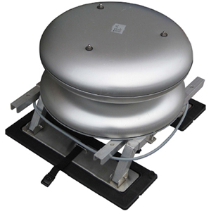
Sound emitter with amplifier TK 150 Mk II for mobile use
Version: KSA666en-SA/1143
1-General
Electronic warning sound emitter TYFONIC ET 500 / 1M mobile is a further development of conventional loudspeaker technology. The result is an omnidirectional sound emitter with the same sound pressure in all directions and high efficiency levels, which help to save energy. The equipment is mainly as a public address loudspeaker and/or as a mobile alert. Amplifier TK 150 MkII is based on digital signal processing, and thus allows audio files to be stored in the common wav format. Siren sounds can be easily downloaded to the amplifier via the USB connection at the rear. Spoken messages through the connected microphone or as audio files previously loaded onto the amplifier permit the rapid communication of information in case of accident or other incidents. Simple connection to a 12 V power output in the vehicle and a vehicle roof connector employing magnetic fixings on the sound emitter shorten mounting time. The vehicle roof connector with magnetic fixings has been tested at different speeds and has a good safety margin at 80 km/h. Optimum speech intelligibility is achieved at a speed of 20 km/h or lower.
2-Mounting
The sound emitter can be mounted on a base of ferromagnetic material
2.1 Lift the loudspeaker vertically out of its box so as not to damage the magnetic feet.
2.2 Clean the magnetic feet using the towel provided.
2.3 Locate the loudspeaker with its magnetic feet at the edge of the vehicle roof.
2.4 Clean the roof at the points which come into contact with the magnetic feet.
2.5 Have a person on either side of the vehicle to lift the loudspeaker into position.
2.6 The fixing devices are telescopic and should be adjusted to each vehicle.
2.7 Tighten the screws after adjustment.
2.8 For extra safety, thread the strap through the rear doors and join together.
2.9 Lifting the loops releases the magnetic feet, enabling the sound emitter to be lifted off.
2.10 The cable from the sound emitter must be introduced into the vehicle through the right-hand passenger door.
2.11 To avoid feedback it is important that doors and windows are firmly closed.

3-Connection
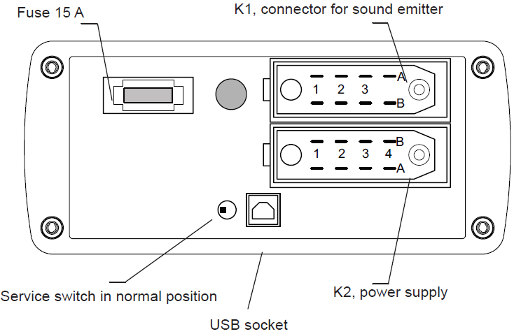
3.1 Place the amplifier on the front passenger seat.

3.2 Connect the cable from the sound emitter to contact K1.
3.3 Connect the power supply cable to contact K2. The red adaptor on the plug allows connection to both 12 and 21 mm sockets.
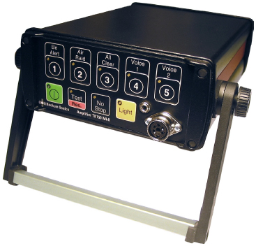
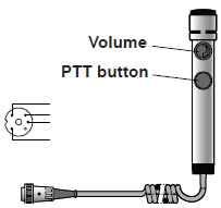
3.4 Connect the microphone to the front with the index screw pointing upwards.
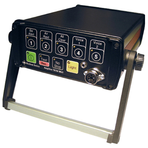
4 Operation


4.1 Use of pre-programmed warning signals.
4.1.1 Start the amplifier by pressing the green button. The LED indicator will light up.
4.1.2 Select the desired signal by pressing button 1, 2 or 3
4.2. Use of recorded messages.
4.2.1 Start the amplifier by pressing the green button. The LED indicator will light up.
4.2.2 Select the desired message by pressing buttons 4 or 5. .
4.3 Use of microphone.
4.3.1 Start the amplifier by pressing the green button. The LED indicator will light up.
4.3.2 Activate the microphone by pressing the PTT button and holding it in while the message is being given. Make sure the volume is turned all the way down before pressing the PTT button. The LEDs in buttons Voice 4-5 will light up when sound is being emitted from the microphone.
4.3.3 Set the volume control on the microphone so as to avoid feedback. Slowly turn up the sound the first time you test the sound. It is most important that all doors and windows in the vehicle are closed to avoid sound from the loudspeakers reaching the microphone.
4.4 Use of external sound source.
4.4.1 Connect the sound source to the input marked “Input”. Use a stereo audio cable with a 3.5 mm plug.
4.4.2 Activate the input by holding in the black button “No Stop” for more than 2 sec onds until the LED indicator gives rapid flashes.
4.4.3 Close line input by pressing the black button “No Stop”.
4.4.4 Disconnect the external sound source.
4.4.5 External sound sources should not be connected or disconnected while the input is activated.
5-Recording
Previously recorded messages in the same storage location will be deleted.
5.1 Record messages either from a line input or the microphone input.
5.2 The amplifier must be activated.
5.3 Press the Test/Rec button until the LEDs on Test/Rec and on Voice 4 and Voice 5 start to flash.
5.4 Select storage location Voice 4 or Voice 5 by pressing the button in question.
5.5 The LED for the selected storage location will give a constant light, while the Test/Rec diode will continue to flash.
5.6 Press the Test/Rec button to start recording. This will cause the diode in the Test/ Rec button to give a constant light while the diode for the selected storage location (Voice 4/Voice 5) will flash once a second during recording.
The maximum recording time for each message is 160 seconds.
5.7 Stop recording by pressing the button for the selected storage location. The diode will shine with a constant light. The light diode on the Test/Rec button will flash rapidly, and the user must confirm that recording is finished by pressing the button.
5.8 When this is done, the LEDs will go out and the amplifier will return to standby.
5.9 Check the sound quality before using the recording.
6-Transport and storage

6.1 All parts of the warning equipment are best stored in the box during storage and transport.
7-Technical specification
| Designation | Rating |
| Soundemitter | ET 500 / 1M |
|---|---|
| Sound pressure level at 1 m distance | 122 dBA |
| Sound propagation | Omnidirectional |
| Temperature range | -30°C...+60°C |
| Ingress protection | IP 54 |
| Height | 420 mm |
| Weight including roof connector | 18 kg |
| Amplifier | TK 150 MkII |
|---|---|
| Power supply | 12 V DC |
| Current consumption | 10 A |
| Output power | 100 W |
| Efficiency | 80 % |
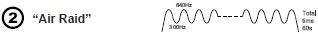
| Warning signals | Be Alert, Air Raid and All Clear |
| Connector | |
|---|---|
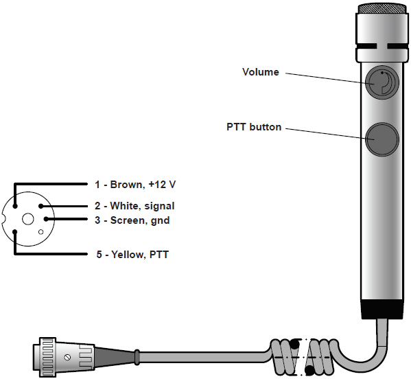
| Mikrofon | DIN 5-polig, 270° |
| Line in | DIN 3.5 mm plug |
| Sound emitter | DIN 41622, RP 622, 8-pole, male |
| Power supply | DIN 41622, RP 622, 8-pole, female |
| Serial communication | USB (type B) |
| Dimensions and weight | |
|---|---|
| Colour | black |
| Dimensions (W x H x D) | 156 x 66 x 220 mm |
| Dimensions with handle (W x H x D) | 182 x 90 x 220 mm |
| Weight | 2.5 kg |
8-Spare parts and accessories
| Designation | Ref. No. |
|---|---|
| Sound emitter complete with roof connector | 24530148 |
| Amplifier TK 150 MkII | 24580298 |
| Fuse, 15 A | 20556109 |
| Connection cable, power supply, 2 m | 20509065 |
| Microphone, Peiker TM 110 | 20141010 |
| Stereo audio cable with 3.5 mm plug, 1.5 m | 42-723-08 |
| USB cable, 1.8 m | 25-576-27 |
| Transport box | 21768748 |
| Compression element | 20620025 |
9-Connectors

10 Troubleshooting
| Symtom | Remedy |
|---|---|
| Amplifier will not start | Check the fuse on the rear. Check/replace the power supply cable. |
| Fuse blows immediately after turning on | Send the amplifier to Kockum Sonics for repair. |
| Pre-programmed signals work, but not the microphone. | Replace microphone. |
11 Preventive maintenance
All functions of the equipment should be tested once a year.