

User Manuel
SOUND EMITTER TYFONIC ET 500/4-1 Ex
Introduction
The Sound Emitter is designed for use in Ex Zone 1.
Precautions
When installing and operating explosion protected electrical equipment, requirements for selection, installation and operation (e.g. IEC 60079-14) must be observed.
Caution
Before making any connections disconnect the power supply. Cable termination should be in accordance with specifications applying to the application. Kockum Sonics recommend that all cables and cores should be fully identified. Ensur that only the correct certified glands are used and that the assembly is shrouded and correctly earthed. Ensure that all nuts, bolts and fixings are secure also not used.
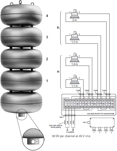
Input connections
The cable from amplifier is to be connected in the Exe junction box in the lowest module of the sound emitter. Terminate the cores to the terminals 1, 2, 3 and 4. Fasten the screws secure even not used.
Specification
| Acoustical Characteristics | Rating |
|---|---|
| Sound Pressure Level @ 1 m | LpA 122 dB |
| Directivity | Omni directional radiation |
| Fundamental Frequency | 370 Hz |
| Frequency Response, f | 240-2500 Hz +/- 3 dB |
| Electrical Characteristics | Rating |
|---|---|
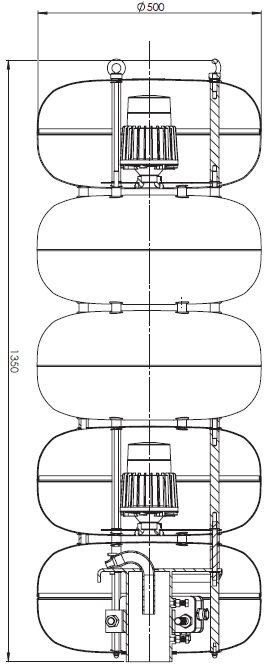
| Number of sound modules and compr. elements | 4 pcs |
| Rated / max voltage / 2 drivers / All clear | 45 V rms |
| Resistance per element | 6,2 ohm |
| Cable gland | M20 |
| Cable diameter | 6…12 mm |
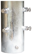
| Earthing | M8 mast foot |
| Environmental Characteristics | Rating |
|---|---|
| Material of sound module | Anodized aluminum |
| Colour of sound module | Natural |
| Material, mast foot | Galvanized steel |
| Suitable mast pole | 3” pipe (outer diameter 89 mm) |
| Operating Temperature | - 50 to + 50°C |
| Storage Temperature | - 50 to + 85°C |
| Degree of Protection | IP 66 |
| Protection class | EEx de IIB+H2 T4 Group II Category 2 G Atmosphere IIB + H2 Zone 1 |
| Temperature class | T4 |
| Size and Weight | Rating |
|---|---|
| Diameter | 500 mm |
| Height | 1400 mm |
| Weight | 42 kg |
| Norm Conformity |
|---|
| 94/9/EC, 73/23/EEC and 89/336/EEC |
| Certification | |
|---|---|
| ATEX coding | 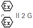 |
| EU Explosive atmosphere symbol Equipment group II Equipment category 2 Atmosphere G | |
| non-mining high level of protection gas | |
| Zone 1 - hazardous atmospheres may be present under normal operation but only for short periods of time. | |
| Certification code | EEx de IIB T4 |
| Certified according to European Ex-standard | E |
| Protection concept | Ex d – flameproof enclosure |
| Protection concept | Ex e – increased safety |
| Gas group | IIA and IIB (not IIC) + H2 |
| Temperature class | T1, T2, T3, T4 (not T5 and T6) |
The product label also carries the mark:
This signifies unit compliance to the relevant European directives, in this case 94/9/EC.
Installation
Use the three lift eyebolts on the top of the sound emitter to place it. The sound emitter ET 500 has a mounting socket for 3” pole (o.d. 89 mm). Fasten the four bolts on the socket and make sure that the counter nuts are secured. Electrical installation in hazardous area must comply with EN 60079-14. Grounding of the equipment has to comply with the ATEX directive. If risk for lightning, connect to building lightning protection with min 16mm2. Local regulations mey be applicable.
Two 17 mm ring spanners are required to fix the locking screws and locknuts. The cables for electric terminals shall be stripped back 8 mm. A suitable screwdriver blade for the terminal screws is 4.0 x 0.8 mm.
The location of the sound emitter is of decisive importance for the warning effect, so it should be located high up and not in a position where adjacent buildings or heights screen the sound. Nor should it be located so high up so that part of the sound will disappear upwards.
The sound emitter should be located on top of the selected building, and not closer than 2 m to the chimney. Buildings located close to main road crossroads are suitable locations, since the sound will travel in a straight line along the streets.
It is important that the sound emitter should be located so high above the ground/street level that it does not cause hearing damage to people who are close to the sound emitter when the alarm is sounded. Nobody should be subjected to sound pressures exceeding 110 dB. As a rule, a sound emitter should not be located lower than 10 m above ground level.
Install the following warning sign beside each installation:
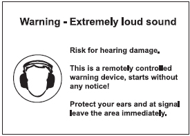
Sign to be put up clearly visible beside the sound emitter.
Maintenance
During the working life of the sound emitter, it should require little or no maintenance. However the amplifier performs impedance tests of the compression drivers automatically once a day. Inspection and maintenance of electrical installations in hazardous area must comply with EN 60079-17.
Troubleshooting guide
The following checklist will assist in the correction of most problems, which you may encounter with your unit. Before going through the checklist below, refer to the connection and operating procedures.
| Symptom | Cause / solution |
|---|---|
| No sound. | The amplifier is in operational mode. > Check the amplifier. |
| Sound not as loud as usually. | One channel in the amplifier is broken. > Check the amplifier. Open circuit in one compression driver element. > Check the service menu at the amplifier and release hardware test, compression drivers. |
Spare parts
Compression driver element, DST-40 EExeN IIB, 8 ohm. Ref no. 20620026
Disposal
The unit shall be handed over to the applicable collection point for the recycling of electrical and electronic equipment. By ensuring this product is disposed of correctly, you will help prevent potential negative consequences for the environment and human health, which could otherwise be caused by inappropriate waste handling of this product. The recycling of materials will help to conserve natural resources.